You might have wondered how industrial facilities accurately measure liquid levels in pressurized vessels without direct visual access. Magnetic level gauge provides a reliable solution that has transformed level measurement in challenging industrial environments.
The magnetic level gauge working principle merges simple physics with clever engineering. These gauges deliver accurate level readings without compromising vessel integrity. A magnetic coupling between a float inside the vessel and external indicators creates a strong and dependable measurement system that works in all types of industrial applications.
This piece breaks down every aspect of magnetic level gauges, from their core components to advanced features. We will show you how these instruments work, get into their key design elements, and explain why they have become the preferred choice for critical level measurement applications in high temperature and high pressure environments.

Understanding the Core Components
Let’s take a closer look at three key components that help magnetic level gauges work naturally. These components work together to give reliable level measurements in challenging industrial environments.
Float and magnetic assembly design

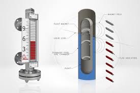
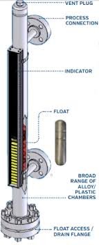
The float assembly is the core of our magnetic level gauge. It contains a sophisticated 360° magnetic system that generates a uniform magnetic circuit. Our team engineers these floats to match each application’s operating conditions. We construct them from various non-magnetic materials like stainless steel, titanium, or PP. The float’s design plays a vital role – it moves freely with the liquid level while keeping precise magnetic coupling with the external indicator.
Bypass chamber construction
The bypass chamber acts as a communicating tube that connects to the main vessel’s sides through at least two process connections. This special design keeps the same liquid level as the main vessel through hydrostatic pressure. Our flanges, pipes, and fittings meet ASME/ANSI design specifications. We offer various construction methods that include extruded outlets and in-line TEE configurations.
Visual indicator mechanism
The visual indicator system has two main types:
- Shuttle Indicators: A follower with an embedded magnet moves freely in a glass column and tracks the float’s position.
- Flag Indicators: Small strips with contrasting colors rotate 180° as the float passes by. They change from white to red for increasing levels and back.
Our indicator system’s unique hermetically sealed design blocks interference from harsh environments and ensures accurate, error-free readings. The magnetic coupling between the float and indicator goes beyond just magnet strength. This careful engineering ensures reliable performance even in demanding conditions like high temperatures and vibrations.
Step-by-Step Working Mechanism
Let’s take a closer look at how these elements work together to measure liquid levels accurately.
Hydrostatic pressure principle
The magnetic level gauge works on a basic principle – hydrostatic pressure. A bypass tube connects vertically to the tank through two flanges. The liquid reaches the same level as the main vessel naturally. Any changes in the tank’s liquid level show up immediately in the bypass chamber.
Magnetic coupling process
The magnetic coupling mechanism forms the core of this system. The specially designed float moves with changing liquid levels while carrying its magnetic assembly. This system stands out because it transmits level data through the chamber wall without physical contact. The float’s magnetic field passes through the non-magnetic chamber wall and creates a strong bond with the external indicator system.
Level indication system operation
The level indication works through these steps:
- The float follows the liquid surface up and down as levels change.
- The float’s magnetic field works with the external indicator system.
- This action turns bi-colored flags or moves a follower in real time.
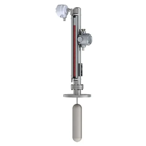
The system measures levels continuously without needing power. It adjusts automatically to changes in density, temperature, and pressure, which gives accurate readings in a variety of conditions. The system can blend with different transmission options that turn magnetic coupling into standard output signals – usually 4-20 mA – to work with remote monitoring and control systems.
Key Design Considerations
The design of magnetic level gauge requires several significant factors to work reliably. Let’s look at what makes these instruments effective.
Material selection criteria
Selecting the right materials is vital for long-term reliability. We used corrosion-resistant materials like austenitic stainless steel and special alloys (Hastelloy®, Inconel®, etc.) to ensure durability. Our materials comply with ASME/ANSI standards for pressure containment. The chamber’s construction uses Schedule 40 thickness. We upgrade to Schedule 80 or 160 in extreme conditions.
These material properties are the foundations of our design:
- High yield strength resists pressure
- Low density matches specific gravity needs
- Anti-corrosive properties protect against aggressive fluids
- Budget-friendly solutions deliver overall value.
Temperature and pressure ratings
Our magnetic level indicator handle tough industrial conditions. Standard configurations withstand pressures up to 6000 psig (414 barg). The temperature range runs from -20°F to 500°F (-29°C to 260°C). Standard gasket materials help maintain these pressure ratings consistently throughout the temperature range.
Float density calculations
Float density calculations determine the accuracy of our magnetic level gauge. The float’s specific gravity (SG) must be lower than the measured liquid’s SG. Temperature variations change specific gravity. These changes are small, but temperature compensation during commissioning ensures optimal accuracy.
Interface level measurements need a minimum specific gravity difference of 0.05 between liquids. To cite an instance, see an oil-water interface where oil (SG 0.7) floats on water (SG 1.0). This difference helps our float detect the interface position accurately making it ideal for applications like magnetic oil level gauges.
Advanced Features and Configurations
Today’s industrial automation world has taken magnetic level gauge way beyond simple level measurement. These sophisticated features make our systems more versatile and reliable.
Remote transmission options
We have revolutionized level monitoring by adding remote transmission capabilities that give real-time data access. Our systems turn magnetic float movements into standardized 4-20mADC outputs. This brings several benefits:
- Real-time monitoring from control rooms
- Better data accuracy and reliability
- Automated data recording and storage
- Less manual readings needed in hazardous areas
Integration with control systems
Our magnetic level indicator merge naturally with modern industrial automation systems. They communicate effectively with SCADA, PLC, and DCS systems. This connection allows sophisticated control capabilities and data management. The system’s value comes from combining on-site indication with remote transmission and control alarm functions. This creates a complete monitoring solution for process media in various industries.
Conclusion
Magnetic level gauges combine basic physics with smart engineering to measure liquid levels accurately in challenging industrial environments. Our team’s careful design choices and advanced features help these instruments give reliable readings. They work without compromising vessel integrity or safety standards.
These gauges have become vital tools in modern industrial applications. Reliable components, precise magnetic coupling, and smart transmission options make them stand out. They just need no power to work and combine smoothly with control systems. Multiple measurement options guarantee steady performance in tough conditions.
Safety, reliability, and accuracy of magnetic level gauge. These instruments excel at measuring both simple liquid levels and complex interfaces. Users appreciate their steady performance and low maintenance needs. Plants looking for trustworthy level measurement solutions will find these gauges a perfect fit, whether it’s a simple sight glass level indicator or a sophisticated magnetic type level gauge with continuous level indication.

